Toggle switches are a simple way to activate accessories in
your car. There are many ways they can be used and wired. Here we will go
through some basic applications and switch types. Note the included diagrams
are for reference only. Always make sure you are using a switch and wire
sufficient to handle the power you are carrying. In higher draw applications, a
relay may be utilized.
Related Articles:
Illuminated Rocker Switch Wiring
Relay Uses and Wiring
If you have any doubts, go to a professional. Improper wiring can
damage your vehicle’s electrical system or cause a fire.
xx
1. SPST Toggle switch (Singe Position, Single Throw)
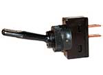
A SPST switch is a simple On – Off switch. They typically have two
terminals. One is for input, the other for output.
In one position the switch is ‘Open’ and no
connection is made, and no power can flow to the accessory. In the other position
the two terminals are connected and power can flow through.
Here is an example of how a SPST might be
wired to power a light.
===================================================================================
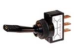
2. SPDT Toggle Switch (Single Position, Dual Throw)
 xx
xx
A SPDT is a bit more sophisticated. It makes one of two connections. Here is
a diagram of a SPDT toggle switch.
Terminal 1 is connected to one load or
accessory, Terminal 3 is connected to another load or accessory. Terminal 2 is
connected to power. The switch is always making one of the two connections and
flips between them. As long as power is connected to the switch, one is always ‘On’.
In the below example the red light is illuminated in one position and the blue
light is illuminated in the other position.
===================================================================================
3. DPDT Toggle Switch (Dual Position, Dual Throw)
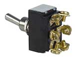
A DPDT switch can be a bit confusing. It might be easiest to consider it to be
two SPDT switches in one. They can connect two different power sources to two
different loads or accessories at the same time. Here is a diagram.
A DPDT switch has six terminals. #3 and #4
connect to the power source. #1, 2, 5 and 6 are for the loads/accessories. In
one position power from terminal 3 is connected to terminal 1, AND power from
terminal 4 is connected to terminal 2. In the other position power from
terminal 3 is connected to terminal 5 AND power from terminal 4 is connected to
terminal 6.
Suppose you had a small cooling fan you
wanted to run on cool days and a larger cooling fan you wanted to run on hot
days. You wanted an indicator to signal which was being used – a blue light for
the small fan, and a red light for the big fan. Here is how you might
accomplish that with a DPDT switch. Note that either one or the other is
running, there is no way to disconnect both fans and lights as long as power is
running to the switch. (Radiator fans can
draw a lot of current, this is an instance where a relay might be warranted –
this is just an example of how a DPDT switch might be used)
SEE OTHER WIRING DEPOT TECH ARTICLES
CHECK OUT THESE WIRING DEPOT TECH VIDEOS